Unconventional Out-of-Band Management using MikroTik LtAP mini-LTE kit and OpenVPN server

Welcome to the dynamic cosmos of networking and connectivity, where the quest for resilient yet budget-friendly solutions takes centre stage. Today, we’re not merely delving into the technical aspects; we’re embarking on a journey into the avant-garde of connectivity solutions – the fusion of the sleek MikroTik LtAP mini-LTE Kit and the powerful OpenVPN.

In this post, brace yourself to unveil the covert potential hidden within the MikroTik LtAP mini-LTE Kit. We’re not merely scratching the surface of its features; we’re unleashing its power and flexibility to provide solutions beyond its initial design. Get ready for a journey where the possibilities of this kit extend far beyond the expected.

What is Out-of-Band (OOB) Management? Now, picture this scenario: You’re overseeing a network device situated miles away from your headquarters. Through the wonders of remote protocols like SSH, you’ve been managing it seamlessly. Suddenly, the device throws a fit, and you are cut off. Oh no! Cue the need for a physical sprint to the device, employing console access to assess the damage – time wasted, money drained, and downtime soaring.

But hold on! What if I told you there’s a smoother way to confirm the device’s status without breaking a sweat? Yes, you guessed it right – Out-of-Band Management! It’s not just a term; it’s the networking world’s century-defining invention, saving you from the hassle of always needing physical access during failures a thing of the past.

While In-Band Management operates through the LAN using conventional remote access methods like SSH, web or Telnet, Out-of-Band Management offers a secure alternative to administering connected devices and IT assets without relying on the corporate LAN – through a separate connection.

Figure 1:Out-of-Band Management
Continue reading “Unconventional Out-of-Band Management using MikroTik LtAP mini-LTE kit and OpenVPN server”

Bridging The Connectivity Gap: Enhancing LTE Antenna Gain To Boost LTE Signal

National Research and Education Networks [NRENs] are expected to connect all R&E [Research & Education] community sites and institutions regardless of physical location or infrastructure presence. This expectation necessitates that the NREN think outside the box to create new and unconventional last-mile solutions. One innovative approach involves boosting the LTE (Long-Term Evolution) connectivity in regions lacking optical fiber infrastructure and those with rugged terrains where it is difficult to deploy microwave point-to-point links due to the difficulty in establishing line-of-sight.

Deployment of Enhanced LTE Setup

The effectiveness of LTE connectivity hinges significantly on the user equipment’s (UE) antenna properties. Antenna gain, a critical factor in signal strength, measures an antenna’s ability to focus its radiation pattern in a specific direction, with higher gains equating to better performance. In areas where the LTE signal exists but is too weak for conventional handheld devices, the solution lies in elevating the antenna gain of outdoor LTE UE devices.

In a series of iterative deployments, the most promising results emerged by utilizing satellite TV offset dishes to enhance the antenna gain of an outdoor LTE UE. The offset dish, functioning as a reflector antenna, catapulted the achieved gain to an impressive 33 dBi. This stands in stark contrast to the 0-3 dBi antenna gain typically achieved on handheld mobile devices allowing for the utilization of LTE service from very distant towers. Consequently, while a standard mobile phone might struggle to detect any LTE signal, the enhanced LTE device equipped with the offset dish registers an equivalent of full LTE signal bars.

The setup of the satellite offset dish and LTE ODU.

The Satellite TV offset dish reflector antenna focuses the incoming signal from the tower onto the LTE ODU positioned at its focal point and it focuses the outgoing signal towards the LTE tower in a beam.

Orientation of the setup with respect to the LTE tower.

Resulting Performance and Latency

The tangible impact of this LTE optimization is evident in the observed performance metrics. The enhanced LTE connection demonstrates a latency of under 50 milliseconds, a substantial improvement that ensures a seamless and responsive user experience. This low-latency connectivity is particularly crucial in regions where traditional satellite solutions would provide a high latency of about 500ms.

Network parameters observed after deployment.

Conclusion

In the pursuit of universal connectivity, NRENs are pushing boundaries and embracing unconventional solutions to bridge the digital divide. The innovative use of satellite TV offset dishes to enhance LTE connectivity showcases the potential for overcoming challenges in underserved regions lacking traditional infrastructure. By achieving remarkable antenna gains and low latency, this approach offers a beacon of hope for communities that have long been left in the shadows of digital isolation. As technology continues to evolve, such creative solutions hold promise for a more inclusive and connected future.

IPv6 Adoption for Future-Proofing

As IPv4 addresses become increasingly scarce, it’s essential for Tier 3 ISPs like RENU to embrace IPv6. Here’s why:

  1. Address Space: IPv6 provides an almost inexhaustible supply of unique IP addresses, ensuring that your network can accommodate the growing number of connected devices.
  2. Improved Security: IPv6 includes built-in security features like IPsec, which enhances data integrity and confidentiality, addressing security concerns more effectively than IPv4.
  3. Global Connectivity: As more organizations worldwide adopt IPv6, ensuring your network supports it enables seamless communication and connectivity with a broader range of peers and services.
  4. Future-Proofing: Transitioning to IPv6 future-proofs your network, ensuring its viability and compatibility as the internet continues to evolve.

High Availability and Redundancy in Network Design

For ISPs like RENU, ensuring high availability is crucial to maintaining uninterrupted services. Here are some strategies for achieving network redundancy:

  1. Redundant Internet Links: Establish multiple internet links from different providers or routes. Implement BGP (Border Gateway Protocol) for dynamic routing to automatically switch traffic to the backup link if one goes down.
  2. Load Balancing: Use load balancers to distribute traffic evenly across multiple network paths. This not only enhances performance but also provides failover capabilities.
  3. Redundant Data Centers: If applicable, replicate critical infrastructure in geographically separated data centers. This ensures that even in the event of a data center failure, services can be quickly restored from the backup site.
  4. Power and Hardware Redundancy: Invest in uninterruptible power supplies (UPS) and redundant hardware components to minimize the impact of power outages or hardware failures.

Ensuring Network Security in a Tier 3 ISP

Network security is a top concern for Tier 3 ISPs like RENU, as cyber threats can disrupt services and compromise data integrity. Here are some essential practices to enhance network security:

  1. Firewalls and Intrusion Detection/Prevention Systems: Deploy robust firewalls and intrusion detection/prevention systems to monitor and filter incoming and outgoing traffic. Regularly update rule sets and configurations to stay ahead of emerging threats.
  2. Access Control and Authentication: Implement strong access controls and authentication mechanisms to ensure that only authorized personnel and devices can access critical network resources. Consider multi-factor authentication for added security.
  3. Regular Patch Management: Keep network equipment and software up-to-date by applying security patches and updates promptly. Vulnerabilities in outdated systems can be exploited by attackers.
  4. Security Awareness Training: Train your staff and users to recognize and respond to security threats. A well-informed team is the first line of defense against social engineering attacks and phishing attempts.

Optimizing Bandwidth Usage in a Tier 3 ISP

In the world of computer networking, efficient bandwidth utilization is paramount, especially for small Tier 3 Internet Service Providers (ISPs) operating in regions like Africa. In this blog post, we’ll explore some strategies for optimizing bandwidth usage in such environments, with a focus on the Research and Education Network for Uganda (RENU).

  1. Traffic Shaping and QoS: Implementing Traffic Shaping and Quality of Service (QoS) policies can help prioritize critical traffic, such as research and education data, over non-essential traffic. This ensures that limited bandwidth resources are allocated efficiently, reducing congestion and enhancing the user experience.
  2. Content Caching: Deploy content caching servers at strategic points in your network. This can significantly reduce the bandwidth needed to deliver frequently accessed content, such as software updates or educational resources, by serving it from a local cache rather than fetching it from the internet each time.
  3. Peering and CDN Partnerships: Establish peering relationships with other ISPs and Content Delivery Network (CDN) providers. By exchanging traffic directly with neighboring networks and leveraging CDNs, you can reduce the load on your international links and improve the speed of content delivery.
  4. Monitoring and Traffic Analysis: Implement network monitoring tools to continuously analyse traffic patterns. By identifying peak usage times and applications consuming excessive bandwidth, you can make informed decisions about capacity planning and policy adjustments.

Q-in-Q Tunneling for ELS support on Juniper Switches

In a network where Service Providers run customers’ VLAN traffic over their backbone network, there is a possibility of VLAN crushing if different customers use overlapping VLAN IDs. With Q-in-Q Tunneling Providers can segregate different customers’ VLAN traffic on a link (for example, if the customers use overlapping VLAN IDs) or bundle different customer VLANs into a single service VLAN.

With Q-in-Q tunneling, providers can segregate or bundle customer traffic into fewer VLANs or different VLANs by adding another layer of 802.1Q tags. Q-in-Q tunneling is useful when customers have overlapping VLAN IDs because the customer’s 802.1Q (dot1Q) VLAN tags are prepended by the service VLAN (S-VLAN) tag.

This makes it a suitable solution for service providers since it gives them freedom on which S-VLANs to use without changing customers’ C-VLANs and customers can use any VLANs they want.


How Q-in-Q Tunneling Works

In Q-in-Q tunneling, as a packet travels from a customer VLAN (C-VLAN) to a service provider’s VLAN (S-VLAN), a customer-specific 802.1Q tag (Customer’s S-VLAN tag) is added to the packet. This additional tag is used to segregate traffic into service-provider-defined service VLANs (S-VLANs). The original customer 802.1Q tag (C-VLAN(s) tag(s)) of the packet remains and is transmitted transparently, passing through the service provider’s network. As the packet leaves the S-VLAN in the downstream direction, the extra 802.1Q tag (Customer’s S-VLAN tag) is removed.

This solution has been illustrated on a Juniper EX-2300-C Switch with Enhanced Layer 2 Software (ELS) support.

There are multiple ways Q-in-Q tunneling maps C-VLAN(s) to S-VLAN(s).

  1. All-in-one bundling
  2. Many-to-one bundling
  3. Many-to-many bundling
  4. Mapping a specific interface

In this tutorial, only “All-in-one bundling” will be covered.

Continue reading “Q-in-Q Tunneling for ELS support on Juniper Switches”

VPLS Multihoming in a Sub-ring setup using rpm and event-handlers for Juniper

Virtual private LAN service (VPLS) multihoming enables you to connect a customer site to two or more PE routers to provide redundant connectivity. A redundant PE router can provide network service to the customer site as soon as a failure is detected. VPLS multihoming helps to maintain VPLS service and traffic forwarding to and from the multihomed site in the event of the following types of network failures:

  • PE router to CPE device link failure
  • PE router failure
  • MPLS-reachability failure between the local PE router and a remote PE router

Ideally, each customer should have dedicated physical connections to PEs, but this kind of setup is expensive for service providers to maintain. Therefore, a new approach of Sub Rings connecting different customers with the use of different VLAN-IDs has been lately utilized as shown below. This makes each CPE logically appear as if it’s connected directly to PEs.

However, VPLS Multihoming was designed to detect failures when the physical interface it’s running on goes down and with this kind of setup, if CPE-2 is multihomed between PE-01 and PE-02 as primary and backup respectively, and the link between CPE-2 and CPE-1 goes down, PE-01 will not notice that failure, therefore, VPLS multihoming will not failover to PE-02 and hence fail-over will not be achieved.

In this blog, we shall cover the set up and configuration of VPLS Multihoming with BGP signaling in a Sub-ring scenario to address the challenge mentioned above.

Continue reading “VPLS Multihoming in a Sub-ring setup using rpm and event-handlers for Juniper”

RECOVERING CISCO NEXUS 3000 SERIES SWITCH USING A TFTP SERVER

INTRODUCTION

Cisco Nexus 3000 Series Switches are designed for data center top-of-rack deployments by providing 24 to 128 ports offering flexible connectivity, high performance, and a comprehensive feature set. It usually runs on multiple versions of OS images including 6.2a, 6.3a, 6.8, 7.3 and many others.

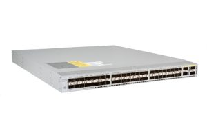
Figure 1: Nexus 3000 series switch

TFTP (Trivial FTP), is a file-transfer protocol geared towards a much simpler, and thus less robust, set of needs as far as file transfers go. TFTP is ideal for transferring of firmware updates, moving system images around, and other tasks that require far more functionality than the traditional FTP. It operates on UDP port 69.

In this article, we are going to recover a Cisco Nexus 3000 Series Switch using images installed on a TFTP server.

SIGNS OF A FAULTY NEXUS SWITCH

  • Continuous booting,
  • Cannot load Operating system image,
  • Cannot read USB drives.

PREREQUISITES

  • In this article, the TFTP server IP address is 168.10.10/24.
  • Ensure the kickstart and main images are stored in the TFTP server and set the TFTP server to use the directory or folder where the files are located.
  • In this article, we shall use n3000-uk9-kickstart.6.0.2.U5.3.bin as our kickstart image and n3000-uk9.6.0.2.U5.3.bin as our file image.


SETTING UP THE TFTP SERVER.

In this article, a Debian-based Linux server with UFW firewall was used to set up the TFTP server as root user.

NB: The configuration on the server IP address is beyond the scope of this article.

  • Install the TFTP server.

# apt-get -y update && apt-get install -y tftp-hpa

  • Configure the TFTP server.

# echo ‘TFTP_USERNAME=”tftp”‘ > /etc/default/tftpd-hpa

# echo ‘TFTP_DIRECTORY=”/srv/tftp”‘ >> /etc/default/tftpd-hpa

# echo ‘TFTP_ADDRESS=”0.0.0.0:69″‘ >> /etc/default/tftpd-hpa

# echo ‘TFTP_OPTIONS=”–secure”‘ >> /etc/default/tftpd-hpa

  • Copy the Cisco recovery images (assuming they are in the current working directory) to the TFTP directory

# cp -n n3000-uk9-kickstart.6.0.2.U5.3.bin /srv/tftp

# cp -n n3000-uk9.6.0.2.U5.3.bin /srv/tftp

  • Start the TFTP service

# systemctl start tftpd-hpa

  • Allow traffic to the TFTP port.

# ufw allow to any port 69


RECOVERING THE NEXUS SWITCH

  • Connect the switch’s Management (MGMT) port (by the power supply) to the network where the TFTP server resides.
  • Configure the switch’s IP reachability using the management port to be able to communicate with the TFTP server.

loader> set ip 192.168.10.4 255.255.255.0

loader> set gw 192.168.10.1

  • Boot the kickstart image file from the TFTP server.

loader>boot tftp://192.168.10.10/n3000-uk9-kickstart.6.0.2.U5.3.bin

  • After a successful boot, you will be directed to the (boot)# From here, you can check whether the boot flash is empty. If empty, copy the files (kickstart image, main image, and license file) over from the TFTP server.
  1. NB. You may need to format the bootflash in case of corrupted condition.
  • If all is well, then copy the kickstart and main image files using the following commands:

switch(boot)#copy tftp://192.168.10.10/n3000-uk9-kickstart.6.0.2.U5.3.bin bootflash:/n3000-uk9-kickstart.6.0.2.U5.3.bin

switch(boot)#copy tftp://192.168.10.10/n3000-uk9.6.0.2.U5.3.bin bootflash:/n3000-uk9.6.0.2.U5.3.bin

  • Verify that both images are in the bootflash using the command:

switch(boot)#dir bootflash:

  • See if the switch is able to boot up using the main image.

switch(boot)#load bootflash:/n3000-uk9.6.0.2.U5.3.bin

  • During the boot, you will be asked whether you would like to enter the initial configuration mode, type This will lead you to the basic configuration, you can then verify your configuration present using the command “show running configuration” in configuration mode.

switch#show running-config

  • Go ahead and reload the switch to ensure that the switch is able to boot up normally.

switch#reload


FURTHER READING

Ping Plotter

Ping Plotter

This is a tool used by the RENU community to troubleshoot network issues. Once an institution is facing problems they are prompted to share their results with the NOC for interpretation. The big question is do you understand these graphs.

This write-up covers the basic features of the graphs and their interpretation.

You’ve captured something in PingPlotter that looks like evidence of a network problem. Let’s take a closer look and see what the graph tells us about the source of your network problem.

Understanding PingPlotter graphs begins with the final destination. That’s the target you’re testing. PingPlotter represents the final destination with the bottom row of the trace graph.

The final destination is the bottom row of the trace graph

Check for packet loss

Take a look at your PingPlotter results. Do you see a red bar? If so, that means some data was lost between your computer and the target. This effect is known as packet loss, and if you’re seeing it on the final destination, there’s a good chance you captured a problem.

Check for latency

What about the black line? It shows how long it takes data to travel to your target and back. This measurement is known as latency. It’s another network problem indicator. The further to the right the black line is the longer it takes for data travel around the network. If you see high latency on your final destination, you’ve probably captured a network problem

Follow the pattern to the source

When you have an idea of what’s happening on the final destination, it’s time to look at the rows leading up to the final destination. Do you notice any patterns leading up to the final destination?

Where the pattern begins, helps you understand the source of the problem. If the pattern starts on the first row in the graph (your router), you’re probably dealing with an internal network problem.

Figure 1 Internal problems begin on the first hop

If the pattern originates somewhere in between the first and last row, the problem is probably outside your local network then contact the NOC it could be problems on the international circuit

Figure 2 Problems outside your network begin in the middle.

.It’s time to make a diagnosis. Do you think the source of your problem is on your local network, or it is it outside your local network?

Wireless Problems

Sometimes other devices interfere with your wireless network. If you connect with ethernet (the cable) and the problem goes away, you probably have a wireless issue.

Bandwidth

Bandwidth problems happen when your network usage exceeds your capacity. If your network problem happens during network-intensive activities like gaming, downloading, or multiple users, there’s a good chance you have a bandwidth issue.

Hardware

When network devices fail, it’s a hardware problem. If you don’t think you’re dealing with bandwidth or wireless issue, it’s time to start looking into hardware.

All the examples above can be categorised as Internal network issues. If you suspect more that the problem is outside your local network contact the NOC.