VPLS Multihoming in a Sub-ring setup using rpm and event-handlers for Juniper
Virtual private LAN service (VPLS) multihoming enables you to connect a customer site to two or more PE routers to provide redundant connectivity. A redundant PE router can provide network service to the customer site as soon as a failure is detected. VPLS multihoming helps to maintain VPLS service and traffic forwarding to and from the multihomed site in the event of the following types of network failures:
- PE router to CPE device link failure
- PE router failure
- MPLS-reachability failure between the local PE router and a remote PE router
Ideally, each customer should have dedicated physical connections to PEs, but this kind of setup is expensive for service providers to maintain. Therefore, a new approach of Sub Rings connecting different customers with the use of different VLAN-IDs has been lately utilized as shown below. This makes each CPE logically appear as if it’s connected directly to PEs.
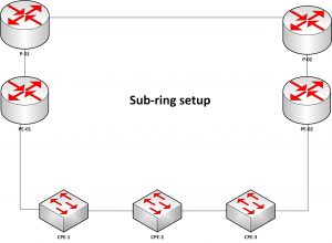
However, VPLS Multihoming was designed to detect failures when the physical interface it’s running on goes down and with this kind of setup, if CPE-2 is multihomed between PE-01 and PE-02 as primary and backup respectively, and the link between CPE-2 and CPE-1 goes down, PE-01 will not notice that failure, therefore, VPLS multihoming will not failover to PE-02 and hence fail-over will not be achieved.
In this blog, we shall cover the set up and configuration of VPLS Multihoming with BGP signaling in a Sub-ring scenario to address the challenge mentioned above.
Requirements:
The configurations were based on the following hardware and software components;
- 4 CPE devices e.g EX2200 or EX2300
- 3 PE devices Juniper MX5, MX480, or any MX series.
- Junos OS Release 12.3 or later running on the PE devices that are connected to the multihomed VPLS site.
Prerequisites:
Assuming the following are in place before configuring VPLS Multihoming. (Configuration of these requirements is beyond this scope.)
- IGP running across the PE routers in your backbone.
- BGP full connectivity configured between PE routers with inet-vpn unicast and l2vpn signaling
- MPLS configured between PE routers with a signaling protocol either resource reservation protocol (rsvp) or label distribution protocol (ldp) but not both.
- Understanding of rpm and event-handlers.
Overview:
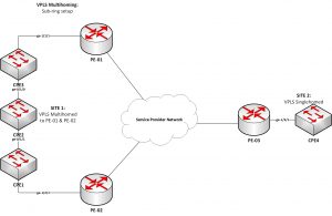
Figure: VPLS Multihoming topology with CPE2 multihomed to PE-01 and PE-02 as primary and backup respectively.
The figure above illustrates CPE2 (site 1) in a sub-ring multihomed to routers PE-01 and PE-02 as primary and backup respectively. CPE4 is single-homed to only PE-03 with two potential paths to reach CPE-2, but only one path is active at a time.
With router PE-01 as the designated VPLS Edge (VE) device (also called a designated forwarder), BGP would signal a pseudowire from router PE-03 to Router PE-01, and traffic from CPE-4 will flow as CPE-4<>PE-03<>Service Provider Backbone<>PE-01<>CPE-02. If a failure occurs over this path, Router PE-02 would be made the designated VE device, and BGP would re-signal the pseudowire from Router PE-03 to Router PE-02, and traffic from CPE-4 will flow as CPE-4<>PE-03<>Service Provider Backbone<>PE-02<>CPE-02.
All PE routers in a VPLS network operate like a large, distributed Ethernet switch to provide Layer 2 services to attached devices.
Configurations:
The following VLAN details shall be used.
VLAN ID 100 – CPE-4 Management with IP subnet 192.168.0.0/29.
VLAN ID 500 – VPLS between site 1 and site 2.
CPE1 and CPE2 should be configured with these necessary VLAN IDs passed on all interfaces facing PE-routers and CPE3.
All configurations are done at the [edit] hierarchy level.
Router PE-03
Configuring sub-interface with VLAN IDs and vpls-encapsulation that support family VPLS
set interfaces ge-1/3/1 unit 500 description “VPLS circuit to Site2”
set interfaces ge-1/3/1 unit 500 encapsulation vlan-vpls
set interfaces ge-1/3/1 unit 500 vlan-id 500
set interfaces ge-1/3/1 unit 500 family vpls
Configuring vpls as singlehomed site.
set routing-instances vpls-example description “SITE2-SITE1 VPLS”
set routing-instances vpls-example instance-type vpls
set routing-instances vpls-example interface ge-1/3/1.500
set routing-instances vpls-example route-distinguisher 500:3
set routing-instances vpls-example vrf-target target:500:500
set routing-instances vpls-example protocols vpls site-range 10
set routing-instances vpls-example protocols vpls no-tunnel-services
set routing-instances vpls-example protocols vpls site SITE_2 site-identifier 2
set routing-instances vpls-example protocols vpls site SITE_2 interface ge-1/3/1.500
set routing-instances vpls-example protocols vpls mac-flush
Router PE-02
Configuring sub-interface with VLAN ID 500 and vpls-encapsulation that support family VPLS
set interfaces ge-1/2/1 unit 500 description ” VPLS circuit to Site1″
set interfaces ge-1/2/1 unit 500 encapsulation vlan-vpls
set interfaces ge-1/2/1 unit 500 vlan-id 500
set interfaces ge-1/2/1 unit 500 family vpls
Configuring vpls-multihoming with this PE-02 designated as backup
set routing-instances vpls-example description “SITE1-SITE2 VPLS”
set routing-instances vpls-example instance-type vpls
set routing-instances vpls-example interface ge-1/2/1.500
set routing-instances vpls-example route-distinguisher 500:2
set routing-instances vpls-example vrf-target target:500:500
set routing-instances vpls-example protocols vpls site-range 10
set routing-instances vpls-example protocols vpls no-tunnel-services
set routing-instances vpls-example protocols vpls site SITE_1 site-identifier 1
set routing-instances vpls-example protocols vpls site SITE_1 multi-homing
set routing-instances vpls-example protocols vpls site SITE_1 site-preference backup
set routing-instances vpls-example protocols vpls site SITE_1 interface ge-1/2/1.500
set routing-instances vpls-example protocols vpls mac-flush
Router PE-01
Configuring sub-interface with VLAN ID 100 for management
set interfaces ge-1/1/1 unit 100 description “Site 1 Management”
set interfaces ge-1/1/1 unit 100 vlan-id 100
set interfaces ge-1/1/1 unit 100 family inet address 192.168.0.1/29
Configuring sub-interface with VLAN ID 500 and vpls-encapsulation that support family VPLS
set interfaces ge-1/1/1 unit 500 description “VPLS circuit to Site1”
set interfaces ge-1/1/1 unit 500 encapsulation vlan-vpls
set interfaces ge-1/1/1 unit 500 vlan-id 500
set interfaces ge-1/1/1 unit 500 family vpls
Configuring vpls-multihoming with this PE designated as primary
set routing-instances vpls-example description “SITE1-SITE2 VPLS”
set routing-instances vpls-example instance-type vpls
set routing-instances vpls-example interface ge-1/1/1.500
set routing-instances vpls-example route-distinguisher 500:1
set routing-instances vpls-example vrf-target target:500:500
set routing-instances vpls-example protocols vpls site-range 10
set routing-instances vpls-example protocols vpls no-tunnel-services
set routing-instances vpls-example protocols vpls site SITE_1 site-identifier 1
set routing-instances vpls-example protocols vpls site SITE_1 multi-homing
set routing-instances vpls-example protocols vpls site SITE_1 site-preference primary
set routing-instances vpls-example protocols vpls site SITE_1 interface ge-1/1/1.500
set routing-instances vpls-example protocols vpls mac-flush
NOTE: PEs that run multihoming should have the same site-identifier but different route-distinguishers.
Switch CPE2
set interfaces ge-0/1/0 description “Link to PE-01 through CPE3”
set interfaces ge-0/1/0 unit 0 family ethernet-switching interface-mode trunk
set interfaces ge-0/1/0 unit 0 family ethernet-switching vlan members 100
set interfaces ge-0/1/0 unit 0 family ethernet-switching vlan members 500
set interfaces ge-0/1/1 description “Link to PE-02 through CPE1”
set interfaces ge-0/1/1 unit 0 family ethernet-switching interface-mode trunk
set interfaces ge-0/1/1 unit 0 family ethernet-switching vlan members 100
set interfaces ge-0/1/1 unit 0 family ethernet-switching vlan members 500
set vlans CPE2-MANAGEMENT vlan-id 100
set vlans CPE2-MANAGEMENT l3-interface irb.100
set vlans SITE1-SITE2_VPLS vlan-id 500
set interfaces irb unit 100 description “CPE2-MANAGEMENT”
set interfaces irb unit 100 family inet address 192.168.0.4/29
We can now leverage the MANAGEMENT connectivity between PE-01(primary node) and CPE2 (site1) and configure rpm with an event handler to track reachability between PE-01 and CPE2.
This will ensure that whenever connectivity is lost, the sub-interface for VPLS with VLAN ID 500 in PE-01 will be deactivated automatically. As a result, VPLS-Multihoming will notice this and notify BGP-VPN about SITE1 not being reachable through PE-01 its primary link and re-route pseudowires through the backup link (PE-02).
With rpm’s continuous checking, when the fault recovers, the event-handler will re-activate the sub-interface and similar updates will be shared again informing all routers about the reachability of CPE2 through its primary link (PE-01) and pseudowires will be re-signaled back through the primary link.
Configuration of rpm and event-handler on PE-01 Router
RPM – Real-time monitoring
set services rpm probe icmp-ping-failure-vpls-example test ping-probe-test probe-type icmp-ping
set services rpm probe icmp-ping-failure-vpls-example test ping-probe-test target address 192.168.0.4 –CPE2 Management IP
set services rpm probe icmp-ping-failure-vpls-example test ping-probe-test test-interval 5
set services rpm probe icmp-ping-failure-vpls-example test ping-probe-test thresholds successive-loss 3
set services rpm probe icmp-ping- success-vpls-example test ping-probe-check probe-type icmp-ping
set services rpm probe icmp-ping- success-vpls-example test ping-probe-check target address 192.168.0.4 –CPE2 Management IP
set services rpm probe icmp-ping- success-vpls-example test ping-probe-check test-interval 5
set services rpm probe icmp-ping- success-vpls-example test ping-probe-check thresholds successive-loss 3
EVENT-HANDLER – Junos Event Automation
set event-options policy deactivate-on-ping-failure events ping_test_failed
set event-options policy deactivate-on-ping-failure within 60 trigger on
set event-options policy deactivate-on-ping-failure within 60 trigger 3
set event-options policy deactivate-on-ping-failure within 65 trigger until
set event-options policy deactivate-on-ping-failure within 65 trigger 4
set event-options policy deactivate-on-ping-failure attributes-match ping_test_failed.test-owner matches icmp-ping-failure-vpls-example
set event-options policy deactivate-on-ping-failure attributes-match ping_test_failed.test-name matches ping-probe-test
set event-options policy deactivate-on-ping-failure then change-configuration commands “deactivate interfaces ge-1/1/1 unit 500” – Deactivate sub-interface after 3 successive ping losses
set event-options policy deactivate-on-ping-failure then change-configuration user-name ehandler-test – local account created with permissions of configuring and committing.
set event-options policy deactivate-on-ping-failure then change-configuration commit-options log “deactivating vpls interfaces for VPLS-Test”
set event-options policy activate-on-ping-success events ping_test_completed
set event-options policy activate-on-ping-success within 60 trigger on
set event-options policy activate-on-ping-success within 60 trigger 3
set event-options policy activate-on-ping-success within 65 trigger until
set event-options policy activate-on-ping-success within 65 trigger 4
set event-options policy activate-on-ping-success attributes-match ping_test_completed.test-owner matches icmp-ping- success-vpls-example
set event-options policy activate-on-ping-success attributes-match ping_test_completed.test-name matches ping-probe-check
set event-options policy activate-on-ping-success then change-configuration commands “activate interfaces ge-1/1/1 unit 500” – activate sub-interface after 3 successive pings received.
set event-options policy activate-on-ping-success then change-configuration user-name ehandler-test – local account created with permissions of configuring and committing.
set event-options policy activate-on-ping-success then change-configuration commit-options log “activating vpls interfaces for VPLS-Test”
NOTE: With multiple RPMs configured for different events it’s advisable to set different time intervals so that the router does not commit different events at the same time.
Important links for further reading
- https://www.juniper.net/documentation/en_US/junos/topics/topic-map/vpls-bgp-multihoming.html
- https://www.juniper.net/documentation/en_US/junos/topics/example/vpls-multihoming-convergence-example.html
- https://www.juniper.net/documentation/en_US/junos/topics/topic-map/vpls-bgp-multihoming.html#jd0e116
- https://www.networkfuntimes.com/junos-rpm-testing-your-juniper-network-with-real-time-performance-monitors/
- https://www.juniper.net/documentation/en_US/src4.12/topics/concept/volume-control-vta-events-handlers-overview.html