Migrating from Zimbra to Zimbra (ZCS to ZCS)

There can be a number of reasons for migrating from one mail server to another, the commonest being “running low on disk storage”. Other reasons may include “the need to having a failover mail server” in case of any catastrophic event that may compromise the active email server, among others.

In other words, this same technique can be used to create a clone of your currently running email server to ensure redundancy.

In order to have virtually zero down time, we will proceed as follows :

  1. Set the DNS TTL Entries pertinent to the mail server to the shortest possible time (Ideally this is done a day before to make sure the ttl propagates accordingly)
  2. Prepare a fully working new server
  3. Import all existing domains from the old server.
  4. Import all existing accounts, passwords, distribution lists, and aliases from the old server
  5. Move all DNS Pointers and firewall port forwards to the new server (or leave the DNS Pointers as they are, and simply swap the servers’ I.P. Addresses old to new, and new to old. (More about this later)
  6. Make sure that new mail is arriving  on the new server.
  7. Make sure users are able to connect and use the new server.
  8. Export Mailbox data from the old server, and import it to the new while the new server is running

Continue reading “Migrating from Zimbra to Zimbra (ZCS to ZCS)”
Q-in-Q Tunneling for ELS support on Juniper Switches

In a network where Service Providers run customers’ VLAN traffic over their backbone network, there is a possibility of VLAN crushing if different customers use overlapping VLAN IDs. With Q-in-Q Tunneling Providers can segregate different customers’ VLAN traffic on a link (for example, if the customers use overlapping VLAN IDs) or bundle different customer VLANs into a single service VLAN.

With Q-in-Q tunneling, providers can segregate or bundle customer traffic into fewer VLANs or different VLANs by adding another layer of 802.1Q tags. Q-in-Q tunneling is useful when customers have overlapping VLAN IDs because the customer’s 802.1Q (dot1Q) VLAN tags are prepended by the service VLAN (S-VLAN) tag.

This makes it a suitable solution for service providers since it gives them freedom on which S-VLANs to use without changing customers’ C-VLANs and customers can use any VLANs they want.


How Q-in-Q Tunneling Works

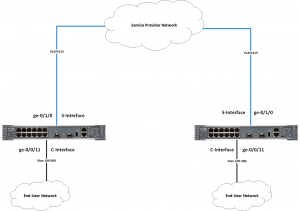
In Q-in-Q tunneling, as a packet travels from a customer VLAN (C-VLAN) to a service provider’s VLAN (S-VLAN), a customer-specific 802.1Q tag (Customer’s S-VLAN tag) is added to the packet. This additional tag is used to segregate traffic into service-provider-defined service VLANs (S-VLANs). The original customer 802.1Q tag (C-VLAN(s) tag(s)) of the packet remains and is transmitted transparently, passing through the service provider’s network. As the packet leaves the S-VLAN in the downstream direction, the extra 802.1Q tag (Customer’s S-VLAN tag) is removed.

This solution has been illustrated on a Juniper EX-2300-C Switch with Enhanced Layer 2 Software (ELS) support.

There are multiple ways Q-in-Q tunneling maps C-VLAN(s) to S-VLAN(s).

  1. All-in-one bundling
  2. Many-to-one bundling
  3. Many-to-many bundling
  4. Mapping a specific interface

In this tutorial, only “All-in-one bundling” will be covered.

Continue reading “Q-in-Q Tunneling for ELS support on Juniper Switches”

VPLS Multihoming in a Sub-ring setup using rpm and event-handlers for Juniper

Virtual private LAN service (VPLS) multihoming enables you to connect a customer site to two or more PE routers to provide redundant connectivity. A redundant PE router can provide network service to the customer site as soon as a failure is detected. VPLS multihoming helps to maintain VPLS service and traffic forwarding to and from the multihomed site in the event of the following types of network failures:

  • PE router to CPE device link failure
  • PE router failure
  • MPLS-reachability failure between the local PE router and a remote PE router

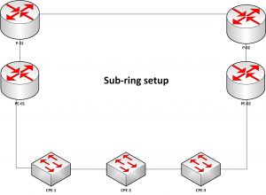
Ideally, each customer should have dedicated physical connections to PEs, but this kind of setup is expensive for service providers to maintain. Therefore, a new approach of Sub Rings connecting different customers with the use of different VLAN-IDs has been lately utilized as shown below. This makes each CPE logically appear as if it’s connected directly to PEs.

However, VPLS Multihoming was designed to detect failures when the physical interface it’s running on goes down and with this kind of setup, if CPE-2 is multihomed between PE-01 and PE-02 as primary and backup respectively, and the link between CPE-2 and CPE-1 goes down, PE-01 will not notice that failure, therefore, VPLS multihoming will not failover to PE-02 and hence fail-over will not be achieved.

In this blog, we shall cover the set up and configuration of VPLS Multihoming with BGP signaling in a Sub-ring scenario to address the challenge mentioned above.

Continue reading “VPLS Multihoming in a Sub-ring setup using rpm and event-handlers for Juniper”