The battlefield of modern network security is ever-shifting, a relentless contest between defenders and those who seek to exploit the network’s weakest links. Among the most deceptive of these threats lies IP spoofing, a technique that cloaks malicious actors behind fabricated identities.
Picture this: a Distributed Denial of Service (DDoS) storm begins to swell. Attackers hide behind forged IP addresses, posing as trusted sources. Your routers, diligent but unsuspecting, focus only on the destination IP, forwarding packets indiscriminately, even the malicious ones.
This is where anti-spoofing comes into play, the quiet guardian that restores order and ensures every packet truly belongs where it claims to come from.
Understanding IP Spoofing
IP Spoofing is the digital art of disguise: a technique where an attacker crafts packets that appear to originate from a trusted source. Technically speaking, IP Source Address Spoofing involves generating IP Packets with forged source addresses rather than those actually assigned to the sending host. In essence, the host pretends to be another system on the network.
Routers, designed to be efficient rather than suspicious, focus on one simple question: “What is the Destination IP Address of this packet, and where should I send it?” They don’t pause to verify whether the Source Address is legitimate. This lack of validation is what makes spoofing both possible and powerful, allowing malicious actors to inject deceptive traffic that appears authentic and masks the true origin of attacks.
Let’s break it down with two simple but deadly tactics: Impersonation and Reflection attacks.
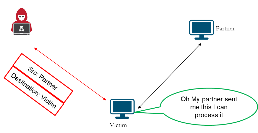
Impersonation Attack
In an Impersonation Attack, the attacker sources packets that seem to originate from a trusted partner or system. By forging the Source IP Address, the attacker effectively impersonates a legitimate host in the communication chain. The victim, unaware of the deception, receives the packet and assumes it’s from a known and authorized source: “Oh, my partner sent me this; I can process it.”
At this point, the attacker gains a dangerous foothold. The system may accept malicious data, execute unauthorized commands, or even open a temporary communication path for deeper compromise. Such attacks often pave the way for more sophisticated exploits like Session Hijacking or Session Reset, where the attacker manipulates or terminates ongoing connections between legitimate hosts.
From a Packet Flow perspective, Impersonation exploits the trust relationship between two endpoints. Because Routers typically validate only the Destination IP and not the Source, the spoofed traffic flows seamlessly through the network, enabling data interception, session disruption, or even full-scale Man-in-the-Middle attacks.
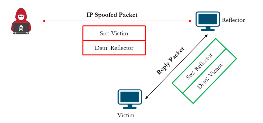
Reflection and Amplification Attack
In a Reflection Attack, the attacker forges packets that appear to come from the victim and sends them to several reflectors, typically servers or devices that automatically reply to incoming requests. Each reflector, believing the request is legitimate, responds to the victim’s IP address, unknowingly helping the attacker flood the victim with a surge of traffic.
Spoofing can be exploited in many ways, but one of the most destructive is the DDoS Reflection and Amplification Attack. In this scenario, the attacker sends small, spoofed queries that trigger disproportionately large responses, amplifying their impact without consuming additional bandwidth.
Common services used as reflectors or amplifiers include open DNS resolvers and NTP servers, both of which can be manipulated to generate massive amounts of traffic directed at a single target.
Reflection attacks take advantage of stateless UDP-based protocols that do not validate source addresses. This loophole allows attackers to conceal their identity while exploiting the bandwidth and processing power of unsuspecting third-party systems to launch overwhelming, large-scale attack.
Defending Against IP Spoofing – The Anti-Spoofing Arsenal
Now that we understand how IP spoofing works, let’s look at how to defend against it. Anti-spoofing measures form the frontline defense against reflection, amplification, and impersonation attacks, ensuring that malicious traffic is filtered before it spreads across the network.
DDoS Reflection and Amplification Attacks would be impossible without spoofing; The solution lies in filtering packets with incorrect or invalid source IP addresses before they leave or enter the network.
The golden rule of network security applies here: stop malicious traffic as close to the source as possible. For service providers, that means implementing protection at two critical points, at client-facing interfaces and at transit or peering interfaces.
At the CPE level, ingress filters can be applied to block spoofed packets originating from customer networks. On the transit and peering edges, BCP38 filtering ensures that only traffic with legitimate source addresses leaves the provider’s network.
To achieve effective anti-spoofing, it’s recommended to adopt ingress filtering methods, which include:
- Access Control Lists (ACLs): Used to validate and allow only legitimate source IP ranges on customer-facing interfaces.
- Unicast Reverse Path Forwarding (uRPF): Verifies the reachability of a packet’s source address through the routing table, dropping any traffic that fails validation.
Technique 1: Access Control Lists (ACLs)
Think of ACLs as bouncers at a club entrance. They check IDs; in this case, source IP addresses, before letting packets in. Only those on the guest list, your trusted subnets, are allowed inside. The rest are stopped at the door.
ACLs serve as the first layer of defense at the network edge, typically applied on CPE devices at client-facing interfaces. They ensure that all inbound packets originate from legitimate client subnets, preventing spoofed traffic from entering the service-provider network.
Below are configuration examples for using both Juniper and MikroTik platforms.
Juniper Example (IPv4 and IPv6)
set interfaces <client-interface> unit <unit> family inet filter input anti-spoof
set interfaces <client-interface> unit <unit> family inet6 filter input anti-spoof

set firewall family inet filter anti-spoof term allowed-prefixes from source-address <client-v4-prefix>
set firewall family inet filter anti-spoof term allowed-prefixes then accept
set firewall family inet filter anti-spoof term spoofed-prefixes then count spoofed-packets
set firewall family inet filter anti-spoof term spoofed-prefixes then reject

set firewall family inet6 filter anti-spoof term allowed-prefixes from source-address <clientv6-prefix>
set firewall family inet6 filter anti-spoof term allowed-prefixes then accept
set firewall family inet6 filter anti-spoof term spoofed-prefixes then count spoofed-packets
set firewall family inet6 filter anti-spoof term spoofed-prefixes then reject
MikroTik Example (IPv4 and IPv6)
/ip firewall filter
add chain=input src-address=<client-v4-prefix> in-interface=<client-interface> action=accept
add chain=input in-interface=<client-interface> action=drop
add chain=forward src-address=<client-v4-prefix> in-interface=<client-interface> action=accept
add chain=forward in-interface=<client-interface> action=drop

/ipv6 firewall filter
add chain=input src-address=<client-v6-prefix> in-interface=<client-interface> action=accept
add chain=input in-interface=<client-interface> action=drop
add chain=forward src-address=<client-v6-prefix> in-interface=<client-interface> action=accept
add chain=forward in-interface=<client-interface> action=drop
Note:
- Always permit ICMP and DHCP traffic as needed before the drop terms.
- Apply ACLs primarily on client-facing interfaces to enforce source validation close to the edge.
- Regularly review and update ACLs when new prefixes or VLANs are introduced to avoid unintended traffic drops.
Technique 2: Unicast Reverse Path Forwarding (uRPF)
If ACLs act as static guards at the door, uRPF is the smart detective inside the network. It inspects every packet’s source address and cross-checks it against the routing table. If the source isn’t reachable, the packet is dropped instantly, preventing spoofed traffic from propagating further into the network.
uRPF operates in two distinct modes:
- Loose Mode: Validates that the source IP exists anywhere in the routing table. It is less restrictive and best suited for core or transit routers, where asymmetric routing may occur.
- Strict Mode: Ensures that a packet arrives on the same interface the router would use to reach the source IP. It’s ideal for access and edge routers, where routing paths are predictable.
Juniper Example (Strict Mode) with filter applied for allowing DHCP and logging.
set security forwarding-options family inet unicast-rpf-mode strict

set firewall family inet filter rpf-filter term allow-dhcp from source-address 0.0.0.0/32
set firewall family inet filter rpf-filter term allow-dhcp from destination-address 255.255.255.255/32
set firewall family inet filter rpf-filter term allow-dhcp then count rpf-dhcp-traffic
set firewall family inet filter rpf-filter term allow-dhcp then accept
set firewall family inet filter rpf-filter term default then count rpf-failed-count
set firewall family inet filter rpf-filter term default then log
set firewall family inet filter rpf-filter term default then reject
This configuration allows DHCP discover and offer packets (which use 0.0.0.0 and 255.255.255.255) to pass successfully, ensuring that legitimate DHCP traffic is not dropped by strict uRPF checks
MikroTik Example (Strict Mode)
/interface ethernet set <client-interface> arp=reply-only
/ip firewall filter add chain=input src-address=!<client-prefix> action=drop
/ip settings set rp-filter=strict
In MikroTik, uRPF is enabled under IP Settings using the rp-filter option. Setting it to strict ensures only packets from known, reachable source subnets are accepted.
Important Considerations
- DHCP Handling: Always permit DHCP traffic explicitly when enforcing uRPF in strict mode. DHCP uses broadcast and special source addresses (0.0.0.0/255.255.255.255) that can fail uRPF validation if not allowed.
- Platform Support: uRPF is supported on select Juniper and MikroTik RouterOS platforms. For devices like EX switches or non-uRPF-capable CPEs, use ingress filters instead.
- Performance Considerations: While lightweight, uRPF introduces additional route lookups. Test carefully in asymmetric routing environments to avoid dropping legitimate traffic.
Technique 3: BCP38 – Network Ingress Filtering at the Peering Edge
BCP38, also known as Network Ingress Filtering, is a best practice that prevents IP address spoofing at the ISP’s Network-to-Network interfaces. While ACLs on CPEs protect individual customer connections, BCP38 filters are applied at peering and transit interfaces to safeguard the ISP’s Autonomous System (ASN) and the global Internet from spoofed or misrouted traffic.
Essentially, BCP38 ensures that only packets with valid source IP addresses belonging to the ISP’s own or customer-assigned prefixes can leave through upstream or peering links. Packets originating from unauthorized or invalid ranges are dropped immediately.
BCP38 filtering serves two main objectives:
- Protecting the Internet from the ISP’s network: Prevents spoofed or misconfigured traffic from customer networks from being advertised to peers and into the wider Internet.
- Protecting the ISP from the Internet: It drops inbound packets with private, reserved, or invalid source addresses received from peers or upstream providers. It also prevents the ISP’s own public prefixes, as well as those of its clients, from being received from its peers.
This two-way protection maintains routing integrity, limits DDoS reflection and amplification attacks, and ensures the ISP contributes clean, authenticated traffic to the global routing system.
BCP38 is implemented at key interconnection points, such as:
- Upstream transit providers
- Internet Exchange Points (IXPs)
- Content delivery peers (CDNs)
These are strategic boundaries where traffic enters or leaves the provider’s core network.
Below is an example of an Outbound filter for protecting the Internet from the ISP ASN both IPv4 and IPv6 applied as an Output filter on all Peering interfaces.
set interfaces <peer-interface> unit <unit> family inet filter output FROM-ISP
set interfaces <peer-interface> unit <unit> family inet6 filter output FROM-ISPv6

set firewall family inet filter FROM-ISP term isp from source-prefix-list ISP-PREFIXES
set firewall family inet filter FROM-ISP term isp then accept
set firewall family inet filter FROM-ISP term client from source-prefix-list CLIENT-PREFIXES
set firewall family inet filter FROM-ISP term client then accept
set firewall family inet filter FROM-ISP term cdn from source-prefix-list CDN-PREFIXES
set firewall family inet filter FROM-ISP term cdn then accept
set firewall family inet filter FROM-ISP term drop then discard

set firewall family inet6 filter FROM-ISPv6 term isp from source-prefix-list ISP-PREFIXES-V6
set firewall family inet6 filter FROM-ISPv6 term isp then accept
set firewall family inet6 filter FROM-ISPv6 term client from source-prefix-list CLIENT-PREFIXES-V6
set firewall family inet6 filter FROM-ISPv6 term client then accept
set firewall family inet6 filter FROM-ISPv6 term cdn from source-prefix-list CDN-PREFIXES-V6
set firewall family inet6 filter FROM-ISPv6 term cdn then accept
set firewall family inet6 filter FROM-ISPv6 term drop then discard
The inbound filter protects the ISP from receiving its own public prefixes and those of its clients from any other ASN, ensuring that any spoofed prefixes containing its own prefixes are dropped on inbound traffic and applied as input on all applicable peering interfaces.
set interfaces <peer-interface> unit <unit> family inet filter input TO-ISP
set interfaces <peer-interface> unit <unit> family inet6 filter input TO-ISPv6

set firewall family inet filter TO-ISP term blk-isp from source-prefix-list ISP-PREFIXESv4
set firewall family inet filter TO-ISP term blk-isp then discard
set firewall family inet filter TO-ISP term blk-client from source-prefix-list ISP-CLIENT-PREFIXESv4
set firewall family inet filter TO-ISP term blk-client then discard
set firewall family inet filter TO-ISP term allow then accept

set firewall family inet6 filter TO-ISPv6 term blk-isp from source-prefix-list ISP-PREFIXESv6
set firewall family inet6 filter TO-ISPv6 term blk-isp then discard
set firewall family inet6 filter TO-ISPv6 term blk-client from source-prefix-list ISP-CLIENT-PREFIXESv6
set firewall family inet6 filter TO-ISPv6 term blk-client then discard
set firewall family inet6 filter TO-ISPv6 term allow then accept
BCP38 acts as the ISP’s global handshake with the Internet; ensuring that only clean, verifiable traffic leaves or enters its network. This not only protects the provider’s ASN but also strengthens the overall security and trust of the Internet ecosystem.
Testing and Verification
After setting up ACLs, uRPF, and BCP38 filters, the next step is to test them and confirm that they effectively block spoofed traffic while allowing legitimate communication to flow freely.
To simulate a real-world attack environment, use tools like Nmap, Python (Scapy), and Wireshark. Nmap and Scapy can generate spoofed TCP and ICMP packets with fake source addresses, mimicking reflection or amplification-style attacks. Wireshark then helps you observe traffic behavior in real time, showing whether your filters are silently dropping the spoofed traffic or letting it through.
Before enabling any anti-spoofing measures, spoofed packets easily reach their target, highlighting how vulnerable an unprotected network can be. Once ACLs, uRPF, or BCP38 are in place, spoofed traffic disappears from the captures, and device counters start recording dropped packets.
You can verify filter activity by running the following commands on Juniper and Mikrotik:
show firewall filter <filter-name>

/ip firewall filter print
The commands display the packet counters for each term in the filter, allowing you to confirm how many packets are being accepted, rejected, or dropped, a clear indicator that the anti-spoofing configuration is actively working.
In practice, this kind of hands-on verification ensures that every defensive layer is doing its job. Using Wireshark and Nmap as part of the testing process provides clear, real-time visibility into how the network responds, proving that the anti-spoofing strategy isn’t just configured, but effective.
Challenges & Lessons Learned
Implementing anti-spoofing controls comes with a few practical considerations:
- uRPF introduces slight processing overhead on routers, particularly in strict mode.
- Anti-spoofing provides limited protection on Layer 2 segments or when the attacker and the victim are on the same LAN, since packets or frames do not traverse the routing table.
- Strict uRPF can block legitimate traffic in networks with asymmetric routing paths.
- ACLs require continuous updating to reflect new prefixes, customer changes, and evolving network structures.
Even with these challenges, the benefits are clear: properly implemented anti-spoofing measures significantly improve the security of both access and backbone networks. Consistent testing and periodic audits ensure configurations remain effective over time.
Wrapping Up
Anti-spoofing is more than a technical feature, it is a mindset. It reinforces network integrity by ensuring that every packet truly originates from where it claims. When ACLs, uRPF, and BCP38 ingress filtering are combined, they create a strong, layered defense that protects both client CPEs and PE layers from spoofed or malicious traffic.
Prevention is always cheaper than mitigation. Stay proactive. Stay protected.
References
- Cisco: Unicast Reverse Path Forwarding Configuration Guide – https://www.cisco.com/c/en/us/td/docs/routers/asr903/sec-data-urpf-xe-3s-asr903-book/m_cfg-unicast-rpf.html
- Juniper: Configuring Unicast RPF – https://www.juniper.net/documentation/us/en/software/junos/security-services/topics/topic-map/interfaces-configuring-unicast-rpf.html